5.10. Digit-serial 8-bit systolic array multiplier
Like VHDL, AleC++ does not favor any logic value system. The logic value system and appropriate lookup tables, overloaded logic operators, basic logic gates, bus resolution functions, etc., can be described in AleC++ and conveniently stored in the library and retrieved when needed.

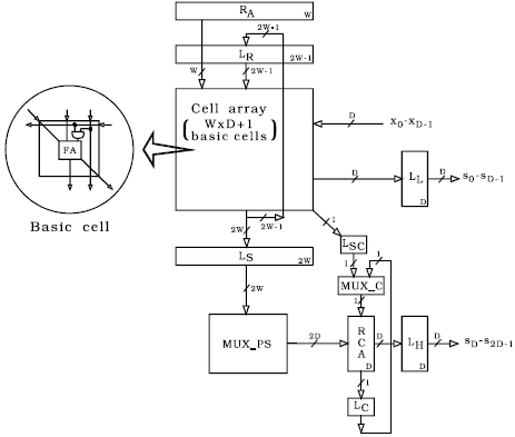
Fig. 5.24: Block diagram of digit-serial semi-systolic multiplier: RA - register for the first operand of multiplication; LR and LS - latch arrays storing partial products; MUX_C - multiplexer 2 to 1; MUX_PS - multiplexer 2W to 2D; LSC and LC - latches; RCA - ripple carry adder; LL and LH - latch arrays storing lower and higher portions of the result; FA - full adder.
The digit-serial multiplier shown in the Fig. 5.24, the building element of more complex semi-systolic architectures [Mile95, Mile96], is simulated using a pre-compiled library developed to emulate the HILO logic simulator [Harr85]. The multiplier is composed of basic processing elements that communicate locally and work in synchronization. The first operand of the length W is available in parallel in register RA, while the second (X) is fed in digit-by-digit, where the number of bits in a digit is marked as D. The multiplier operates in two phases: in the first phase the lower portion of the product is generated at the outputs s0-sD-1, while the other half is available in the second phase at the outputs sD-s2D-1.
Let us illustrate the multiplier modeling by showing the simplified model of full adder, which is part of the systolic array basic element, as shown in Fig. 5.20. Firstly, the model class fadd is defined.
// model parameters defined with min, typical and max value
typedef double param[3];
// different delays from inputs to outputs, direction flags
# define FROM_AB 0
# define FROM_CIN 1
# define TO_SUM 0
# define TO_COUT 1
# define TAKE_MAX_DELAY -1
// full adders model class
class fadd {
param delay01[2][2];// rising edge propagation delay
param delay10[2][2];// falling edge propagation delay
fadd();
>fadd();
public:
// delay function
double ADDdelay (three_t, three_t, int, int);
friend module fa;
};
Full adder module is described with the following code.
module fadd::fa (fift_t in a, b, c_in; fift_t out sum, c_out) {
action { process (a, b, c_in) {
three_t a3, b3, c_in3, sum_result, cout_result; int from_in;
// detect active input
if((a->event || b->event) && c_in->stable)
from_in = FROM_AB;
else if( c_in->event && a->stable && b->stable)
from_in = FROM_CIN;
else { // simultaneous event at (a or b)/c_in
warning("fadd::fa - simultaneous (a or b)/c_in change");
from_in = TAKE_MAX_DELAY;
}
// convert input states to three_t
// log. operations are not held in HILO 's 15-st. log.
// system (fift_t), but in 3-state system (three_t).
a3 = Con15to3[a];
b3 = Con15to3[b];
c_in3 = Con15to3[c_in];
// evaluate logic function
sum_result = a3 ^ b3 ^ c_in3;
cout_result = (a3 & c_in3) | (a3 & b3) | (b3 & c_in3);
sum <- Con3to15[sum_result] after
this->ADDdelay(sum_result, Con15to3[sum],
from_in, TO_SUM);
c_out <- Con3to15[cout_result)] after
this->ADDdelay(cout_result, Con15to3[c_out], from_in, TO_COUT);
} // process (a, b, c_in)
} // action
} // module fadd::fa ()
The above code is part of mentioned Alecsis library for HILO emulation. In order to use the module fa in multiplier description for simulation, user has to connect the library file and to define its model card. One particular model card for a full adder module is as follows.
model add15::fa_1 {
// {min value, typ value, max value}
delay01[FROM_AB][TO_COUT] = {0.2ns, 0.5ns, 1.0ns};
delay10[FROM_AB][TO_COUT] = {0.3ns, 0.6ns, 1.5ns};
delay01[FROM_CIN][TO_COUT]= {0.3ns, 0.5ns, 1.3ns};
delay10[FROM_CIN][TO_COUT]= {0.3ns, 0.6ns, 1.5ns};
delay01[FROM_AB][TO_SUM] = {1.3ns, 2.4ns, 5.6ns};
delay10[FROM_AB][TO_SUM] = {0.9ns, 2.2ns, 6.0ns};
delay01[FROM_CIN][TO_SUM] = {0.5ns, 0.9ns, 2.0ns};
delay10[FROM_CIN][TO_SUM] = {0.4ns, 0.9ns, 2.7ns};
}
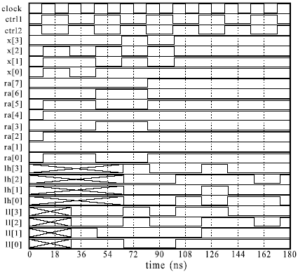
The multiplier is simulated at gate level, using generic structures that enabled the word length to be passed as an action parameter. An example of the simulation results for the configuration with W=8 and D=4 is shown in the Fig. 5.25. The entire circuit contains more than 500 gates modeled with more than 1000 concurrent processes, while around 25000 events were handled during the simulation. It took 4.76 CPU seconds to simulate the circuit using Alecsis implementation on Hewlett-Packard Series 9000/375 platform with Motorola MC68020 processor. The simulation results obtained using HILO logic simulator were identical. Unfortunately, HILO was implemented on a different platform and simulation times were not comparable.

Fig. 5.25: Example of simulation results for 8-bit configuration of the multiplier from Fig. 5.24: clock, ctrl1 and ctrl2 are global control signals; x[0] - x[3] are inputs for second operand; ra[0] - ra[7] are RA outputs (first operand); lh[0] - lh[3] are the outputs of LH; ll[0] - ll[3] are the outputs of LL.

